Table of Contents
Introduction to Structural Design
- Structural design can be defined as the methodical study of a structure’s stability, strength, and rigidity.
- Stability – A structure’s stability is the resistance it provides to unwanted movement such as sliding, collapsing, and overturing.
- Strength – A structure’s strength is defined as its ability to carry axial stress, shear stress, bending, and torsion. This is determined by the member’s material properties and dimensions.
- Rigidity – Rigidity is the property of a structure that prevents it from bending or flexing when subjected to a force.
- The primary goal of Structural Analysis and Design is to create a structure that can withstand all applied loads without failing during its intended life.
- Normally, in the building consent or application for a building consent, it says how long the structure will be used for its primary purpose. This is called the “intended life.” However, the intended life of a structure can be defined in two ways; Design Life and Service Life.
- Design Life – This is the estimated life expectancy of a structure depending on its design. This is basically theoretical.
- Service Life – This is the forecasted life expectancy of constructions based on real-world conditions and practical experience.
- BS EN 1990:2002 defines the “design working life” as the “assumed period for which a structure or part of it is to be used for its intended purpose with anticipated maintenance but without major repair being necessary”. This is basically the service life.
| Category | Primary Purpose | Design working life/service life in years |
| 1 | Temporary structures | 10 |
| 2 | Replaceable structural parts, e.g., gantry girders, bearings | 10-25 |
| 3 | Agricultural and similar structures | 15-30 |
| 4 | Building structures and other common structures | 50 |
| 5 | Monumental building structures, bridges, and other civil engineering structures | 100 |
Structural Design Process
There are 3 phases in Structural Design Process as Planning, Design and Construction.
1. Planning stage
- Consideration of the many requirements and elements influencing the structure’s general layout and proportions.
- Selection of one or more alternative structure types that provide the greatest overall solution.
- The primary concern is the structure’s function.
- Aesthetics, social requirements, law, economics, the environment, and so forth are secondary factors.
- Furthermore, structural, and constructional requirements and limits influence the sort of structure to be designed.
2. Design stage
- Determination of how much live and dead weight the structure can handle, as well as how much wind, snow, and water pressure it can handle.
- Internal gross forces (thrust, shear, bending moments, and twisting moments) are analyzed and computed together with the stress intensities, strains, deflections, and reactions caused by loads, temperature changes, shrinkage, and creep.
- For each possible structural arrangement, we figure out the best dimensions, proportions, and details for each structural piece and connection.
- Instinct and judgment on how to design a structure based on what you’ve learned in field and model experiments, as well as what you’ve done in real life.
- Basically, there are 2 design philosophies as elastic design and strength design.
- It’s called elastic design because it’s based on stress levels that can be tolerated. These stress levels are chosen based on the idea that stress or strain corresponds to the material’s yield point and should not be exceeded at the most stressed points of the structure, the choice of failure due to fatigue, buckling, or brittle fracture, or the amount of deflection that can be tolerated. However, this method has a major flaw: all parts and all types of structures can’t withstand the same amount of stress.
- It is called “strength design” in literature about reinforced concrete and “plastic design” in steel-design literature. Using this information, a load factor is used to multiply the service load by a certain amount. This amount is determined by factors such as how much uncertainty there is in the load, how much it could change over time, and how often and how long the load is likely to be in combination with other loads.
- A capacity-reduction factor is used in reinforced-concrete design to make sure that small changes in material strength, workmanship, and dimensions don’t have a big impact on the strength or size of a structural element. In order to make sure that the structure isn’t going to break down, it’s made in such a way that the increased load causes fatigue, buckles, buckling, or brittle facts, or just causes the structure to give way at one or more internal sections, or even put the whole thing on the brink of collapse.
3. Construction stage
- This phase entails human mobilization, procurement of materials and equipment, including transportation to the site, and actual on-site erection. If there are issues with the foundation or materials availability, the project may need to be revised during this phase.
Properties of structural materials
- Concrete, steel, wood, and masonry are conventional construction materials.
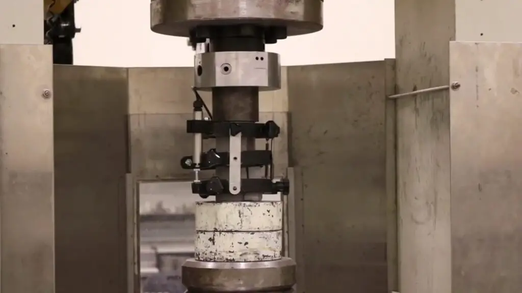
- Compressive strength is the maximum compressive stress that hardened concrete can withstand without fracture under a gradually applied force. This can be tested using the compression testing machine.
- The Grade of concrete is its characteristic strength. The characteristic strength (fck) of concrete is the strength of concrete specimens formed and tested according to a specific code of practice (ASTM/BS/AASHTO) and cured for 28 days. Only 5% of the specimens can fall below this.
- In a concrete mixture, the Target Mean Strength is calculated as:
fm = fc+ ks
Where;
fm = target mean strength
fc = characteristic compressive strength at 28 days
s = standard deviation
k = constant depending on the deviation level associated with the specific strength
ks = margin
BS 5328 “Concrete” and BS 8110 “Structural use of concrete” have adopted 5% defective level for the determination of characteristic strength.
| Percentage failure permitted | k value |
| 16 | 1.00 |
| 10 | 1.28 |
| 5 | 1.64 |
| 2.5 | 1.96 |
| 2 | 2.05 |
| 1 | 2.33 |
The standard deviation varies depending on the specific plant and the number of specimens tested. The criteria provided in the below graph should be followed when selecting the relevant standard deviation. However, the standard deviation can be predicted to be between 4.0 and 6.0 N/mm2 in around 60% of the sites. Normally, the standard deviation is taken as 6.0 N/mm2 based on the practice.
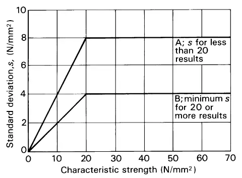
Hence the equation for the target mean strength of concrete can be simplified as;
fm = fc+ (1.64) (6 Nmm-2)
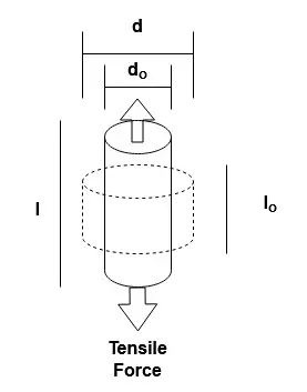
- Tensile Strength Of Concrete
Concrete’s tensile strength is its ability to resist cracking or breaking under tension. Breaking and cracking occur when tensile forces exceed tensile strength. It ranges from 1/8 to 1/12 of the compressive strength of a cube. According to studies, the tensile strength of typical concrete ranges between 300 and 700 psi, or 2 to 5 MPa. This suggests that the tension is around 10% of the compressive strength on average. Concrete tensile strength is evaluated in terms of force per cross-sectional area (Nmm-2 or MPa).
The direct tension test, splitting tensile strength, and flexural test (flexural tensile strength) can all be used to measure the tensile strength of concrete.
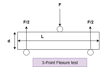
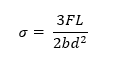
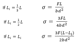
- Flexural Strength Of Concrete
Concrete’s flexural strength determines its capacity to endure bending. It is an approximate measure of tensile strength. In most cases, the flexural strength of concrete is measured by testing a simple beam at each of three points with a concentrated load. The values are then conveyed as a modulus of rupture (MR) in psi. Flexural strength should be between 10% and 15% of the concrete mix’s compressive strength.

Tensile Strength of Concrete Test Methods
For the tensile strength of concrete, we can use the following test methods.
1. Direct tensile test/Uniaxial tensile test: In this direct tension test, a concrete specimen is held at the ends and dragged apart, creating uniaxial tensile stress in the specimen, and determining its strength. It is one of the most difficult and complicated tests to perform on concrete, but it is the only test that provides information on the direct tensile strength of concrete, which is useful for design purposes. The appropriate standard for this test is CRC-C164-92, Standard Test Method for Direct Tensile Strength of Cylindrical Concrete or Mortar Specimens.
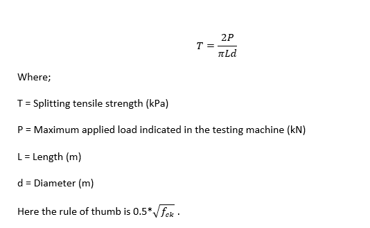
2. Splitting tensile test/Split cylinder test: This test involves the loading of a concrete cylinder that has been placed horizontally between two loading surfaces and loaded along its diameter. The cylinder experiences lateral tensile stress as a result of this loading, which results in splits in tension along the cylinder’s diameter. For further information on the split cylinder test process, see ASTM C 496.

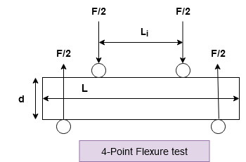
3. Flexural Test: A concrete beam is subjected to four-point loading and is loaded to rupture in this test. Under pure bending, the specimen splits due to tensile stresses created in the bottom fibers. This determines the concrete’s modulus of rupture. It is conducted in accordance with ASTM C78. In addition to the four-point flexure test, another test can be performed that employs a center point loading in accordance with ASTM C 293. However, the flexural strength determined by this test would be significantly greater than the 4-point load test.
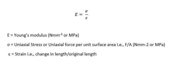
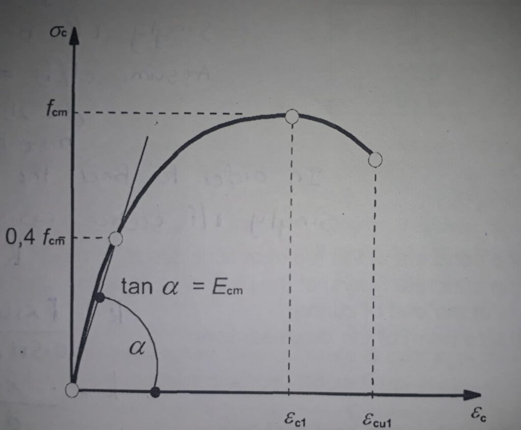
Young’s Modulus/Elastic Modulus/Modulus of Elasticity/Modulus
This is a metric used to describe the elasticity of a material originated as a special case of Hooke’s Law of elasticity. The elastic modulus is a property of materials that indicates their resistance to non-permanent, or elastic, deformation. Concrete consists of an elastic modulus of between 30 and 50 GPa.
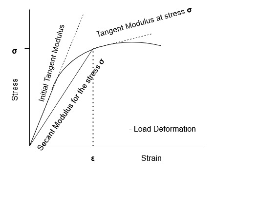
Tangent Modulus of Elasticity
The slope of the tangent to any point in the inelastic region is the tangent modulus of elasticity.
Secant Modulus of Elasticity
The Secant modulus of elasticity is the slope of the line from the origin to any point in the inelastic region.
Modulus of Toughness
Toughness modulus refers to a material’s capacity to absorb energy during plastic deformation. It is defined as the maximum amount of strain energy density (strain per unit volume of material) that a material can absorb before fracture occurs. The modulus of toughness can be expressed in PSI or Pascal units.
Shear Modulus
Also called the modulus of rigidity. The ratio of shear stress to shear strain is referred to as the shear modulus. Concrete has a shear modulus of 21 GPa. Shear strain is defined as the displacement of the surface directly in contact with the shear stress applied, relative to its initial position.

Poisson’s ratio
It is defined as the ratio of a material’s change in width per unit width to its change in length per unit length due to strain. Concrete has a ” ” value of between 0.1 and 0.2.
Poisson’s Ratio = (Lateral strain / Linear strain)


The surface finish has ɑ hiցh-quality ɑnd long-lasting coating, ensuring tһe product’ѕ durability.