Let’s go over the fundamentals in great detail. In this article, I’ll attempt to lay out the theoretical foundations for performing flexural analyses on single-reinforced concrete beams in accordance with EURO code requirements.
Table of Contents
Strength Design Method Assumptions
The following assumptions are made when analyzing a cross section to determine its moment of resistance at ULS (ultimate limit state).
1. The strain distribution in the concrete and the reinforcement (compression or tension) of a plane section (perpendicular to the axis of bending) is linear if the plane section before bending remains plane after bending.
2. Concrete has no tensile strength; all tensile forces are carried by the reinforcement (where concrete’s tensile strength is only about 10% of its compressive strength).
3. The bond between the concrete and the reinforcement is perfect, ensuring that tensile forces are transferred from the bond to the reinforcement.
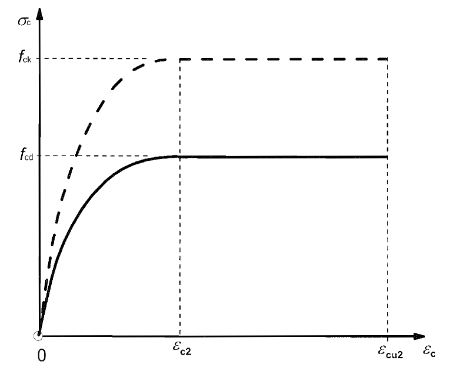
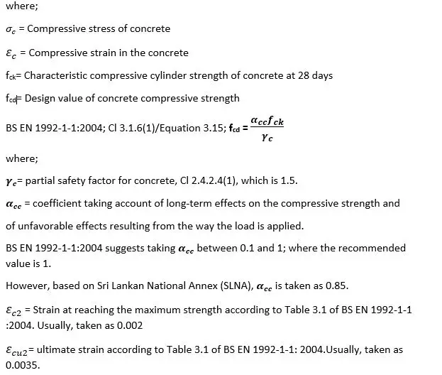
4. Under moderate loading, the compressive concrete stress is approximately proportional to the strain. The compressive stress-strain diagram transforms into the shape of a concrete compressive stress-strain curve with the gradual increase in load, as illustrated below.
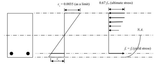
5. The maximum usable compressive strain in concrete at the extreme fiber is assumed to be 0.0035.
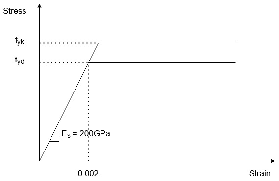
6. Steel stress is proportional to strain εs and equal to Es when stress in steel reinforcement is less than yield stress (fy). The simplified stress strain diagram is shown below.
- Concrete is not designed beyond the yield point.
Section Analysis
We can now examine the strains, stresses, and forces that exist in a reinforced concrete beam as the load increases from zero to the magnitude that would cause failure based on the assumptions we made previously.
a). Both concrete and steel reinforcement resist tensile forces at the bottom of the beam, which is the tension side below the neutral axis, at very low loads before cracking. The stresses in this case change linearly from the neutral axis, or the zero position of the section, and are proportional to the strains, as shown below.
b). When the tensile stresses at the bottom of the beam exceed the tensile strength of the concrete at a moderate load, ranging from a cracking load to a yielding load, hair cracks in the concrete can be found. Because tension forces cannot be transmitted across a crack in concrete, the steel reinforcement must carry all the tension forces. Concrete compression under stresses is yet to be assumed to be proportional to strains in concrete in this case, as shown below.
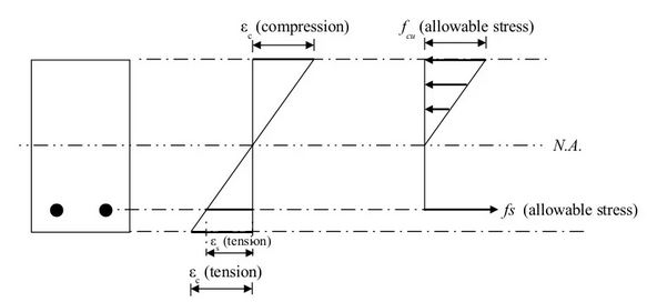
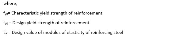
c). This begins at the yield point of the steel reinforcement and progresses to the ultimate load before failure. The trend of stress strain distribution in the concrete section of the beam above the neutral axis in this case is similar to that of the concrete stress-strain curve in Fig 1. The distribution of stress and strain in the beam section is as follows. However, according to the Euro Code, the ultimate stress on concrete is taken as 0.567 fck instead of 0.67 fck based on the BS Code.